
The following story, covering the International Air Transport Association Technology Road Map for 2050 (short form IATA TRM 2050), will cover additional technologies slated for introduction in the 2023 – 2030 timeline.
These technologies are considered to be focused on reducing in-flight requirements and, as such, are recognized as interim measures rather than long-term plans. But as claimed previously, the discipline in pursuing the short-term will support how the long-term challenges are approached and resolved.
This web story will cover the Open Rotor, the UHAR Wing Demonstrator, and the continuation of more Electric Control Surfaces (known as Fly By Wire) for all aircraft classes.
Open Rotor
We presented an in-depth story on the Open Rotor in October 2022. Please see this link for more complete coverage of this topic.
The IATA TRM states that Safran’s RISE (Revolutionary Innovation for Sustainable Engines) Program intends to test an open Rotor on the A380 test bed. Figure 1 shows the artist’s concept of the Open Rotor fan in flight.
Figure 1: The Open Rotor is illustrated on an A380 aircraft in flight. Note this is an artist’s concept only.
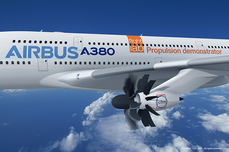
The Open Rotor is scheduled to enter the demonstration stage only after 2025 through the RISE program. A partnership is indicated between Airbus (the aircraft manufacturer) and CFM (the engine manufacturer) to support these program developments. CFM is a partnership in the form of a joint venture between GE Aerospace and Safran Aircraft Engines. These partnerships will aim to carry out a flight test demonstrator program on the Airbus A380 and validate the open-fan engine architecture.
Part of this and related technology development initiatives is to build a foundation for the next-generation CFM engines, which are planned to use 20% less fuel and create 20% fewer emissions. These benefits would be incremental to any jet engine in use today, and the open rotor is intended to enter service by the mid-2030s.
Part of the benefits of the open rotor is that an engine case does not surround the rotor itself. This reduces the engine’s weight and allows for the fan blades’ design to be even longer, bringing further benefits from the design. As a result, the engine fan can now move much higher volumes of air around the gas turbine engine rather than try to push all the air through the engine core. An open rotor fan could achieve a bypass ratio above 70:1. Currently, the best bypass ratio is 12:1. These future higher bypass ratios will further reduce fuel consumption and emissions.
UHAR Wing Demonstrator
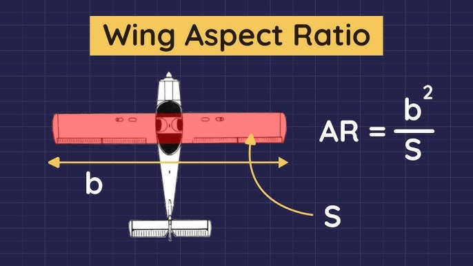
The acronym UHAR refers to the Ultra-High Aspect Ratio wings, which are related to efforts to redesign aircraft wings. These efforts intend to reduce aircraft drag. Figure 2 provides a simple diagram of just what is the Aspect Ratio and how it is calculated.
For a more detailed description of how the aspect ratio is calculated, please see this YouTube Video (What is aspect ratio?).
Figure 2: A Simple Diagram of the Wing Aspect Ratio calculation
As can be imagined, the UHAR technology intends to go beyond the current wing designs, as shown in Figure 3.
Figure 3: Comparison of two contrasting Aspect Ratio designs
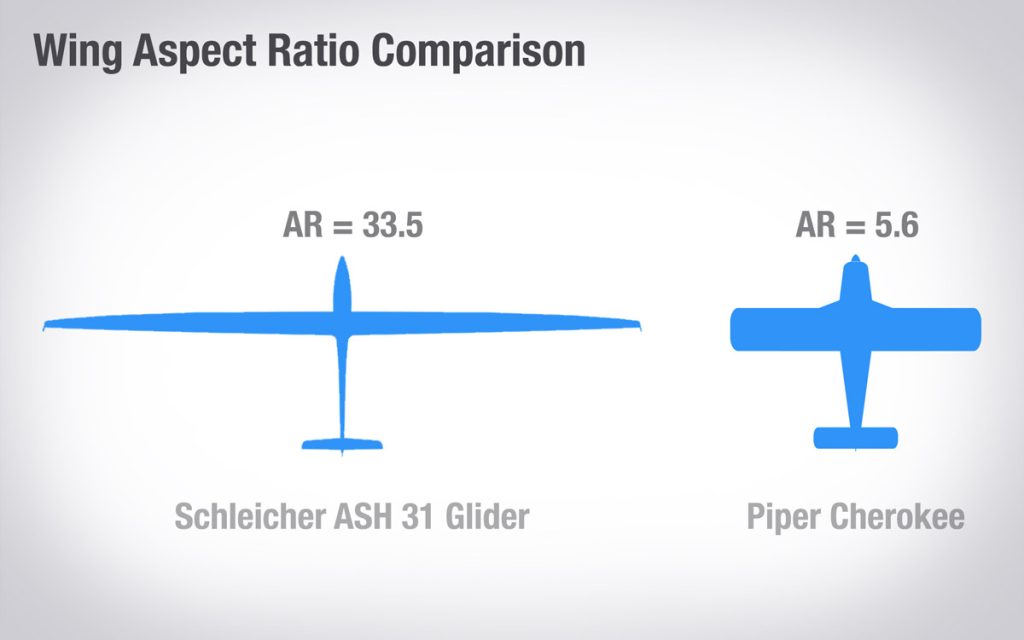
Figure 3 shows that redesign can radically alter the Aspect Ratio. In this case, the ratio has been improved by 6x for the aircraft on the left of the picture compared to the one on the right. The advantages of these designs are that as the wingtip has less area, there is less induced drag from the downwash coming from the end of the wing. This induced drag has its greatest effects at low speeds and high altitudes. As a result, aircraft with these improved designs perform very well in takeoff, climb and cruise stages. As a result, high-aspect wings perform better throughout most flight stages!
Nevertheless, such wings bring new challenges in that they are less maneuverable, and as they are thinner, they need more structure (i.e. materials) to compensate for those new designs. Lastly, there is the issue of fuel placement. A thinner wing means less space for fuel, meaning that fuel may need to be placed in the aircraft’s body.
The UHAR technology, however, has some distance to go yet as it is currently being worked on through computer simulations and wind tunnel tests. Before flight tests could be planned for this technology, “bench tests” would take place at the Airbus Extra Performing Wing Demonstrator. Following these stages, proven designs could be implemented on civil aircraft, as indicated in the IATA roadmap.
Electric Control Surfaces
An earlier EnviroTREC web story discussed how the Boeing 787 was one of the first aircraft to enter into service with more electric flight control systems. A further point was that the aerospace industry understands that considerable opportunities exist to deploy these types of technologies to all future-generation aircraft. The IATA 2050 roadmap reiterates this point and encourages others to follow suit.
To see our earlier story on this topic, please click this link.
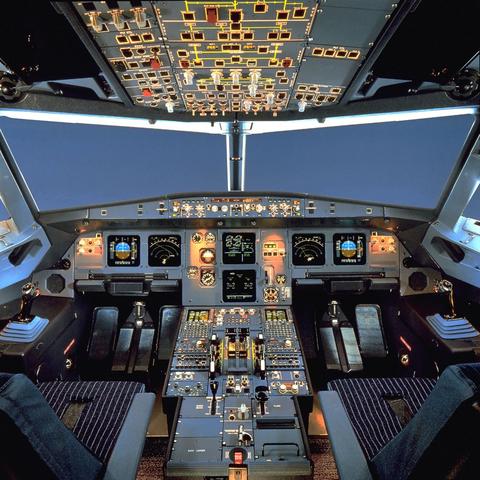
To add to the IATA comments, the Airbus A320 family has been adopting this technology since 1984. Figure 4 shows a presentation of Fly by Wire (FBW) in the cockpit.
Figure 4: The cockpit of a FBW Airbus 320
An important point to make about FBW is that the loss of all flight control computers immediately renders the aircraft uncontrollable. Backups are necessary to compensate for such events. Most fly-by-wire systems incorporate redundant computers (and batteries!). Mechanical or hydraulic backups sometimes provide the needed redundancy, perhaps even a combination of both systems. Some aircraft FBW systems may be quadruplexed (i.e. four independent channels) to prevent loss of signals so that in the case of failure of one or even two channels, the system is still up and operable.
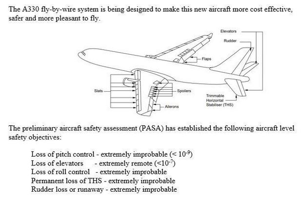
Figure 5 shows some FBW considerations in the design process.
Other benefits of FBW systems are that they may require less maintenance than traditional systems since they have fewer moving parts and are less susceptible to wear and tear. FBW technology can also enhance an aircraft’s stability and maneuverability, making it more agile and capable of precise maneuvers. Additionally, FBW systems can simplify aircraft control and handling, potentially reducing the training time required for pilots to become certified to fly the aircraft.
In conclusion, in this story, we have seen how the Open Rotor, the Ultra-High Aspect Ratio wing redesign, and Fly by Wire are being implemented in the near future to improve in-flight efficiencies.
A few technologies still remain to be covered for near-term flight improvements, after which we will cover fuel selection and designs for the future.