
Several stories have been posted on our website concerning the IATA (International Air Transport Association) Technology Roadmap. The most recent TRM from this industry organization makes a considerable shift from previous versions, which were assembled with the assistance of their members and other stakeholders.
The first significant change is that while previous TRMs were technology-driven, they did not have an endpoint. At the end of their timeline, there was no particular final achievement.
Now, the IATA Aircraft Technology Net Zero Roadmap (2023) does have an endpoint for the aerospace industry: to support achieving a zero CO2 emissions goal by 2050.
Contributions to building this TRM came from reports from announced technology demonstrator programs by Original Equipment Manufacturers (OEMs) and national research centers. Additionally, publicly available reports, including certain technology strategies, were incorporated into this report. Finally, company websites were reviewed, and public conference presentations were also considered. Experts from industry and academia were also solicited to weigh in and provide their input. Lastly, IATA convened specific engagements between their organization and stakeholders to provide additional and requisite depth to this piece.
The roadmap that was produced deliberately overemphasized the pre-2035 timeframe. IATA’s reasons here were that decisions made in the earlier timeframe would impact later decision points in the roadmap and, indeed, for the Industry. The future points to one that will support new aircraft types and some considerable technology changes that were not anticipated earlier.
The following web stories will break down the IATA Net-Zero TRM into several working pieces. The first part will be a three-part set on Reducing In-Flight Energy.
Reducing In-Flight Energy, Part 1
The problem that reducing in-flight energy brings us is that certain technological developments will each reduce in-flight energy by modest amounts (i.e. 3 – 5 %), with the next generation providing a 20% overall improvement when these increments are added. The overall impact of energy demand for aviation services is that energy requirements will outpace the in-flight features that are under development or are yet to be introduced. These technological developments are “grist for the mill,” as later improvements will call upon the lessons learned and configurations achieved to develop further novel configurations that may rely on those earlier systems.
Figure 1: Reducing In-Flight Energy
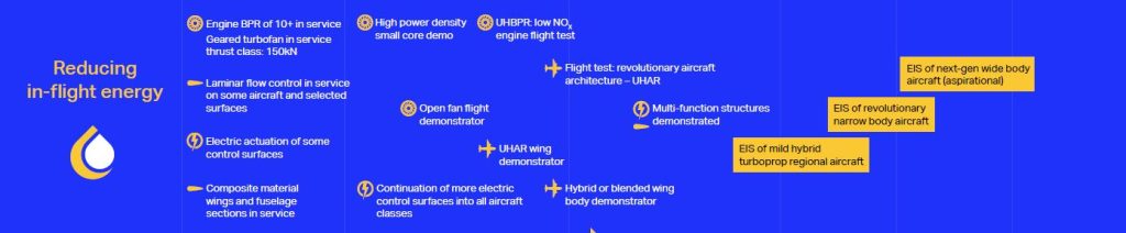
We will examine the specific features of Figure 1 over the following stories, to which a table will be added for further detailed examination
- Engine ByPass Ratio
At the top of Figure 1, it is indicated that reducing in-flight energy is currently being achieved using engine bypass ratio technology. Over the past two decades, this has modestly impacted the aerospace industry. The first company to attempt this development was Pratt & Whitney, which is currently claimed to have achieved an Engine BPR ratio of over 10. The EBPR refers to the ratio of air in the jet engine that bypasses the combustion chamber versus the air that goes through the core. A high bypass ratio reduces energy consumption and reduces emissions. Other manufacturers (RR + GE) have also pursued this technology. To support the EBPR, a planetary gearbox needs to be added to the engine configuration. This planetary gearbox is located between the low-pressure compressor/turbine and the fan, enabling each fan to spin at its optimum speed.
Figure 2: Evolution of the Turbofan Bypass Ratio
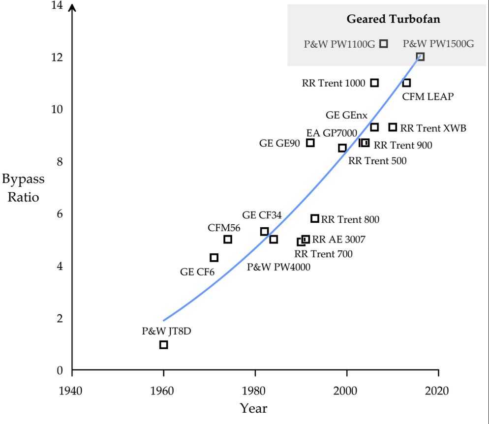
Figure 2 provides more details of how the turbofan has evolved, its principal developers, and its current state of the art. The P&W PW 1100G and the P&W PW 1500G are indicated to have bypass ratios exceeding 12, with the trend moving ever upwards.
The thrust range of many of these gas turbine engines is from 18,500 to 34,000 lbf (pounds of force), or 82 to 150 kN (kilo Newtons). Examples of these power levels are found with the gas turbine engines configured for the A220, A320neo family, and Embraer E-Jet E2.
2. Laminar Flow Control
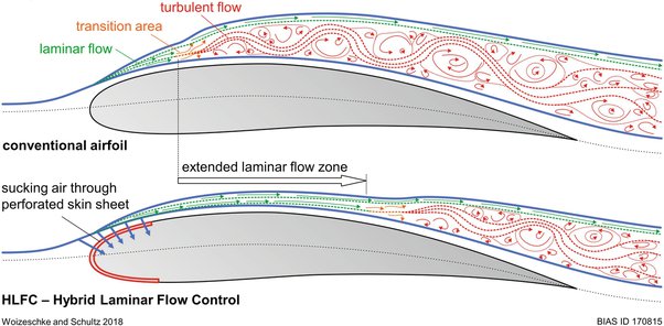
Laminar flow control is another area of energy gain from inflight operations. This area is slowly gaining ground with this technology found on some aircraft on selected services. One example is the B787, which is indicated to use laminar flow control on the tail. This concept uses the suction of a small quantity of air through airplane (i.e. tail) surfaces and offers the potential for a significant reduction in drag, thereby resulting in large increases in range or decreases in fuel usage for aircraft.
An interesting story on Laminar Flow Control technology can be found here: Laminar Flow Control Takes Hold on the Airbus A340.
Figure 3: Comparison of a Conventional Airfoil vs One Using Laminar Flow Control
3. Electric Actuation of Some Aircraft Surfaces
A common understanding of modern aircraft assemblies is that they are filled with duplicated hydraulic systems. These types of controls are modestly weighted due to their pipes, actuators, and operating fluid.
There are opportunities to reduce aircraft weight by shrinking aircraft actuators through efficiency gains and continuing to substitute hydraulic systems (which rely on pumps, valves, motors, actuators, pipelines and fittings) with simpler and lighter electric systems. In these cases, the piping, controls, etc., are replaced by wires. Electric motors and related systems are found at the endpoint, eliminating all the previously used hardware throughout these processes. Such systems are also referred to as “fly by wire.”
The Boeing 787 was one of the first aircraft to enter into service with more electric flight control systems. The Aerospace industry realizes there are considerable opportunities to deploy similar technologies to all future-generation aircraft, as indicated in the roadmap. Another opportunity for system weight reduction is better integration of systems within the structure; for example, antennas can be embedded in the fuselage skin, thereby reducing both weight and drag.
Figure 4: Electromechanical and Related Actuation Technologies Deployed in a modern aircraft
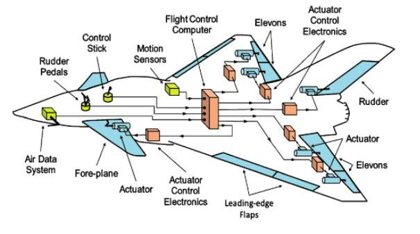
Figure 4 shows the complexity that needs to be considered when replacing hydraulic systems with electromechanical units. Nevertheless, it also clearly indicates the “wired” systems related to aircraft control.
Weight gains here are often quoted in modest terms; however, these increments add up when several systems are combined. One military aircraft was indicated to have a 600 -1000 lb take-off weight reduction through the application of “fly by wire.”
Figure 5: A Presentation of Aircraft Hydraulic Systems
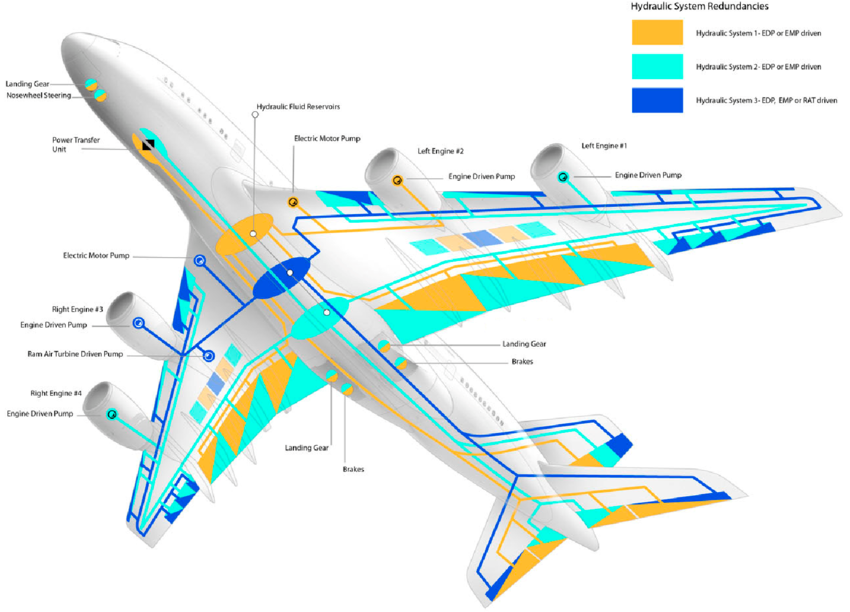
Pneumatic systems for aircraft are indicated in Figure 5. These systems persist as they are now well understood, easier to maintain, and highly reliable.
This now concludes the first of three parts of the IATA Net Zero TRM. The following stories will continue to cover further topics for reducing in-flight weight, such as the implementation of Composite Materials.
References used in this web story:
2. EnviroTREC: Laminar Flow Control Takes Hold on the Airbus A340