
Two final pieces on Reducing In-Flight Energy are found on the IATA TRM 2023. These items are rather unique as they represent a timeline some years out. These timelines point to the period of 2030 to 2035 for the presentation of these technologies in certified and deployed form.
We will present some notes dealing with the first of these two topics: Multi-Functional Structures, or MFS.
The first of these technologies is the demonstration of multi-function structures in aircraft. Many options seem to present themselves here, including structural elements with more than one function. An example of this would be antennas embedded in the fuselage. These items would, for example, reduce the weight of both items by being combined meaningfully during manufacture. One item provides structural support, while the other supports systems integration.
The typical passenger jet can have 30 to 50 antennas protruding from the aircraft’s external surface. These protruding antennas create drag forces that can drastically reduce fuel efficiency; all of this is going on while aircraft manufacturers are trying to convince their customers that they are trying to minimize in-flight energy consumption. Most antenna applications support safety purposes, such as air traffic control, traffic collision avoidance, instrument landing systems and distance measuring equipment. Recent additions, though, of antennas have been made to meet passengers’ demands by providing new services such as Wi-Fi access, in-flight TV, and cellphone service.
When aircraft skins were originally made of aluminum, antennas needed to be placed on the aircraft’s surface because aluminum would block the signal to or from the antenna. Now, with carbon-based composites being used for many critical structural components on an airplane, antenna design is being re-evaluated to see whether it is possible to embed these antennas inside the fuselage to reduce drag and improve operational efficiency.
These aircraft antennas require omnidirectional transmission; that is, radiation transmission needs to be distributed in a spherical pattern with the antenna as the origin. Furthermore, these various signals need to be transmitted and received reliably from any direction. Two examples are provided here. The first is from a UAV that needs ground control to provide guidance and keep it on mission. In this case, the UAV combines its name with its capabilities as an Integrated Steerable Antenna for Beyond Visual Line-of-sight L-band data Exchange (ISABELLE). The application of the MFS technology to a non-passenger application allows for the vetting of the technology and processes needed to apply to a passenger project later.
Figure 1: UAV with Integrated Steerable Antenna for Beyond Visual Line-of-sight L-band data Exchange
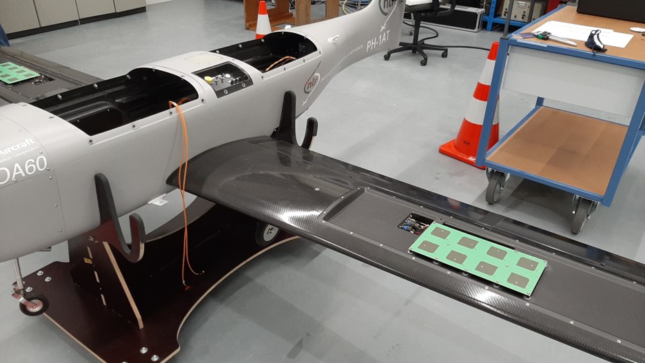
The development of this UAV follows from the diversity of potential applications that have been identified over time. Among the earliest applications of UAVs for civil use have been the so-called dull, dirty or dangerous tasks, such as performing oil and gas exploration surveys. ISABELLE has been developed to operate Beyond Visual Line Of Sight (BVLOS). In order to maintain control, the operator needs a SATCOM link between the UAV and the Remote Pilot Station (RPS). The importance of the antenna placement and design comes from the fact that lightweighting is very important for BVLOS missions, which are long-term and require a priority emphasis on battery management.
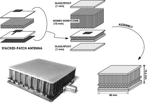
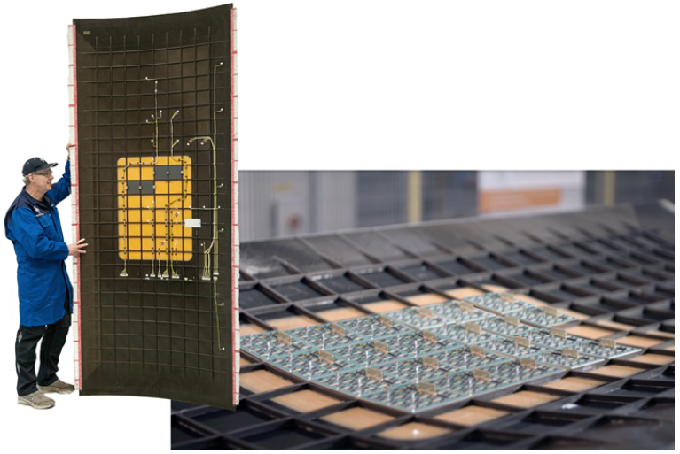
The second example of MFS is indicated in Figure 2 and is also from the Netherlands Aerospace Centre. Their ACASOAS ( Advanced Concepts for Aero-Structures with Integrated Antennas and Sensors) project demonstrates a 1.2 x 3-meter fuselage panel into which a 4 X 6 array of Ku-band antenna elements have been integrated. The array sits within a glass fibre composite “window” in the outer skin for RF transparency. These panels are supported with an orthogonal grid of CFRP (carbon fibre-reinforced plastic) panel stiffeners.
Figure 2 Multi-functional Fuselage Panel
MFS – Structures that dissipate heat
On the most superficial level, the increased use of electronics in aircraft has been considerable. As these electronic systems become more significant, through moving to fly-by-wire systems, these aircraft begin to present a heat dissipation challenge. As shown in Figure 3, an aircraft has many sources of surplus heat which need to be dissipated.
Figure 3: Sources and Sinks for Heat on Aircraft
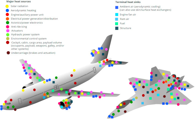
While electronics are indicated to be one source of excess heat, there are many other sources, such as solar radiation (the skin of an airplane), engine units, aerodynamic heating, and many others. Figure 3 demonstrates that the methods by which this heat is dissipated also vary.
Due to the challenges presented in aerospace, unique methods also need to be attempted. One of these unique methods is the use of porous and lattice structures. These structures are being tested for application in the thermal management of aircraft and other aerospace vehicles. Figure 4 demonstrates several examples of thermal management of porous and lattice structures, allowing air to circulate between the layers and removing excess heat.
Figure 4: Several common lattice structures with different unit elements
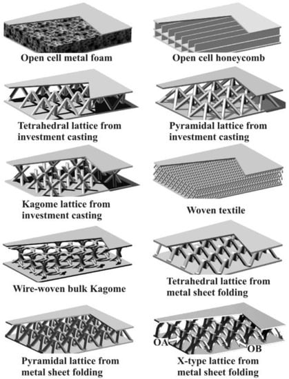
These types of structures are used as airplane skins and placed in critical areas for maximum effect.
To further demonstrate this work on MFS (Multi-Functional Structures), Figure 5 shows how the redesign of certain electronic components supports the integration of a multi-chip module into an aerospace structural panel, further contributing to these applications. F
Figure 5: Multi-Functional Structure panel, including the structural panel with integral thermal control
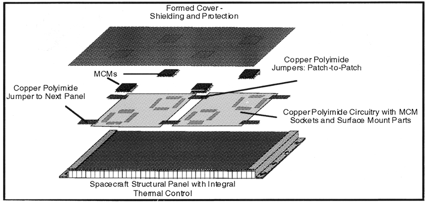
This design approach uses a multi-chip module (MCM), which is an electronic package comprising of multiple integrated circuits (ICs) that are assembled into a single device. This device is then integrated into the airplane’s skin, supporting weight and strength management objectives while saving space.
In conclusion, Multi-Functional Structures (MFS) are an innovative concept that offers a new methodology for spacecraft and aerospace design by eliminating chassis, cables and connectors and integrating the electronics into the walls of the spacecraft. The MFS design consists of multilayer flexible circuit patches bonded onto a structural composite panel along with the multichip modules. These systems are proving to be effective and capable of being used in aerospace applications.
The IATA TRM shows that the MFS technology is coming forward at a modest pace. Our publications research indicates that these MFS technologies have been under development for about 25 years. This lengthy delay in deployment indicates aerospace’s challenges in moving forward when technologies are not yet developed despite having a new airplane design on the drawing boards.
We see that early deployment, in some cases, takes place in applications that do not involve humans as passengers or pilots, thereby attempting to prove the technology’s effectiveness without creating excessive risks.