
Ubiquitous Composites are supporting the evolving Gas Turbine Engine Cycle in a number of ways. But gathering materials for the second part of this story[1] on the Engine Cycle proved challenging as background materials and ideas were not provided in the referenced IATA TRM. Figure 1 provides a cut from a table found in the IATA report, that identifies a general comment and reference.
Figure 1: Engine Cycle Cut Out From the List of Retrofits and Upgrades Available for GT Engines Before 2030, IATA TRM 2017[2]

Ubiquitous Composites are indicated in Figure 1 as becoming a part of the engine cycle and are predicted to be able to improve fuel efficiency by 10 – 15%.
There is little further context to this in the IATA TRM 2017 (or TRM 2013). However, the FAA Center of Excellence for Alternative Jet Fuels & Environment provides a much better context and explanation, from which we can present the following webstory.
Figure 2: A Further Representation of the Retrofits and Upgrades Available for Aircraft[3]
| Category | First Generation | Second Generation | Third Generation |
| Engine Cycle | |||
| Engine Structures and Materials | CMC Nozzle Advanced TBC Coatings | Ubiquitous Composites Advanced turbine superalloys | Advanced powder metallurgy disk Blisk and Bling concept |
Figure 2, however, drops Ubiquitous Composites from being a direct part of a reimagined engine cycle, such as Adaptive/Active Flow Control (which we wrote about in an earlier story on this website1), to now being part of Engine Structures and Materials. Again, this revision makes more sense when compared to the first-generation and third-generation products.
Figure 2 shows that the engine structure has been improved as a first-generation project through the use of the CMC (Ceramic Matrix Composite) nozzles and advanced TBCs (Thermal Barrier Coatings).
This First-Generation CMC component development activity facilitates high firing temperatures in the gas turbine engine. The development of this technology will furthermore build upon CMC capability advancements made under earlier DOE programs. Improved Gas Turbine engine performance was accomplished through enhanced designs and concepts, better sealing, reduced leakage, and leveraging advanced manufacturing processes to facilitate high-performing turbomachinery. These revolutionary CMC components will now be deployed to improve the gas turbine performance in combined-cycle applications, such as in combined gas and steam plants. Also benefitting from this technological advancement in the future will be the gas turbines used in coal-based IGCC (Integrated Gasification Combined Cycle) applications with pre-combustion carbon capture and producing hydrogen as the resulting fuel[4].
The second item from Figure 2, the First Generation of Engine Structures and Materials, refers to TBC Coatings. Thermal Barrier Coatings (TBCs) are applied to metallic surfaces in gas turbines and support exhaust heat management. These coatings are between 100 μm to 2 mm in thickness and help the combustion process by thermally insulating the internal components of gas turbines from significant and prolonged heat loads. These components can now sustain an appreciable temperature difference between the load-bearing alloys and the coating surfaces. The sole reason for working with higher temperatures in this environment is to increase engine efficiency by raising the combustion and exhaust temperatures of the gas turbine. These First Generation materials are believed to have achieved their performance limit, and pursuing the second generation of materials is now underway.
Figure 3: Utilization of TBC – in a First-Generation Engine Structures and Materials Application

Thermal barrier coating (coloured white) on a turbine guide vane in a V2500 turbofan engine.
Source: International Aero Engines AG
The second generation of Engine Structures and Materials raises Ubiquitous composites and Advanced turbine superalloys as the leading products expected to advance gas turbine technologies in the coming years. One key goal for these materials is to achieve the >1700oC gas inlet goal. The gas inlet is the hottest part of the gas turbine engine, and any gains here translate into engine efficiency. Developments here are focused on additional composite layered components in the gas turbine engine and advanced superalloys to replace the current alloys used in the engine structure. Some of the proposed solutions here use rare earth metals bound to silicate oxides. But these applications are quite challenging as up to three layers of specialized materials need to be applied using thermal spray systems. Each layer deposited resolves the problem of adhering to the preceding substrate while contributing to the ultimate solution.
SiC-based CMCs undergo active oxidation and recession (i.e. loss of material) in the high-temperature, high-pressure, high-velocity gas stream of the gas-turbine engine, as things now stand. This gas stream invariably contains steam which is a combustion byproduct. To overcome the degradation effects of this high temperature and high-pressure steam and other combustion byproducts, new dense and crack-free environmental barrier coatings (EBCs) are needed to protect the SiC-based CMCs. ECBs accomplish this by blocking the diffusion and ingression of oxygen and steam into the gas turbine engine components.
In Generation 3, Engine Structures and Materials – Advanced Powder Metallurgy Disk and, Blisk and Bling concept are raised as potential sources of improvements to the engine cycle. Since Generation 2 is yet to be solved, the next generation of materials and processes are yet to be created. The first suggestion in Generation 3 is to use advanced power metallurgy to create gas turbine disks. A gas turbine usually comprises a set of disks fastened onto a shaft. Generally, disks feature profiled pockets with various complex clearance requirements. These complex components are difficult to machine (Figure 3) and use advanced alloys such as Inconel 706.
Generation 3 is indicated to advance from machined materials to Advanced Powder Metallurgy. This new material will be either pressed, sintered or isostatically hipped.
The second part of Generation 3 Engine Structures and Materials refers to the Blisk and Bling concept.
The terms Blisk and Bling are combination names for combined gas turbine engine functions. BLING refers to a Bladed Disk while BLING refers to a Bladed Ring.
Figure 4: Comparison of Engine Blade Ring Designs – the BLISK and the BLING
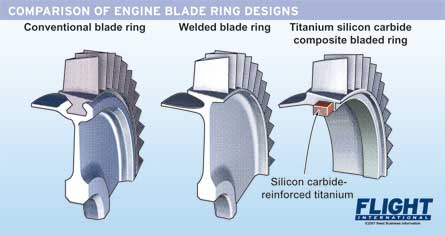
Source: FlightGlobal
In a conventional engine rotor (leftmost part of Figure 4), individual blades are slotted into the disc rim. In bladed discs, or blisks (centre part of Figure 4), the blades are welded directly to the rim of the rotor. This change in design can itself provide a 30% weight saving. To move on to producing a bling (rightmost part of Figure 4), a ring with integral blades is first wound as a composite preform, then encapsulated in a titanium alloy forging. By using high-strength silicon carbide-reinforced titanium, less metal is needed, further reducing the overall weight of the part[5]. Reducing the weight of any part of the aircraft improves its overall operating efficiency. The Blisk-Bling combination will itself be able also to improve the engine efficiency by between 10- 15%. This is identified as a later 3rd Generation advancement because the engine is being recomposed in the 2nd Generation developments. With those changes will come new operating temperatures and regimes. Once the second-generation enhancements and determinations are made, then the third-generation enhancements can proceed.
What this web story has drawn together are three generations of gas turbine engine materials development and their effect on the engine cycle. Namely that as the engine temperatures are able to be increased along with weight reduction of engine component parts, then overall efficiencies will improve between 10 – 15%.
While the IATA TRM shows these advancements as post-2020, we are well past that now, and these changes will likely take place in the later part of this decade.
[1] Our first part on the Engine Cycle story is found at: https://www.envirotrec.ca/2023/coming-soon-the-adaptive-active-flow-control-gas-turbine-engine/
[2] Aircraft Technology Roadmap to 2050, https://www.iata.org/contentassets/8d19e716636a47c184e7221c77563c93/Technology-roadmap-2050.pdf
[3] Project 10 Aircraft Technology Modeling And Assessment; Phase One Report, FAA Center of Excellence for Alternative Jet Fuels & Environment https://s3.wp.wsu.edu/uploads/sites/192/2017/10/ASCENT_P10_2017_PhaseI_Final_Report.pdf
[4] Our first part on the Engine Cycle story is found at: https://www.envirotrec.ca/2023/coming-soon-the-adaptive-active-flow-control-gas-turbine-engin
[5] https://www.flightglobal.com/rolls-royce-tests-material-to-give-jsf-engine-some-bling-/73991.article