
Our next web story continues with how the aviation and aerospace industries have assembled a roadmap for Net-Zero.
This next story poses three approaches for reducing the in-flight energy requirements of aircraft. The following three ideas are deploying composites, creating higher gas turbine power density, and building gas turbine engines with low NOx combustion gasses.
The discussion of each of these technologies now proceeds as follows:
1. Using composite material in wings and fuselage sections and bringing additive manufacturing online.
It is well understood that further reductions in aircraft weight can be achieved by continuing to pursue the use of composite materials, particularly in the narrow-body market, which currently has limited use of this novel material!
The aerospace industry understands that aircraft made from composite materials take longer to build than those with metal-based parts. Enabling high-rate composite parts production becomes a critical industry requirement and requires significant tooling and manufacturing systems investments. This all leads to decreased manufacturing cycles, accelerating the introduction of new aircraft.
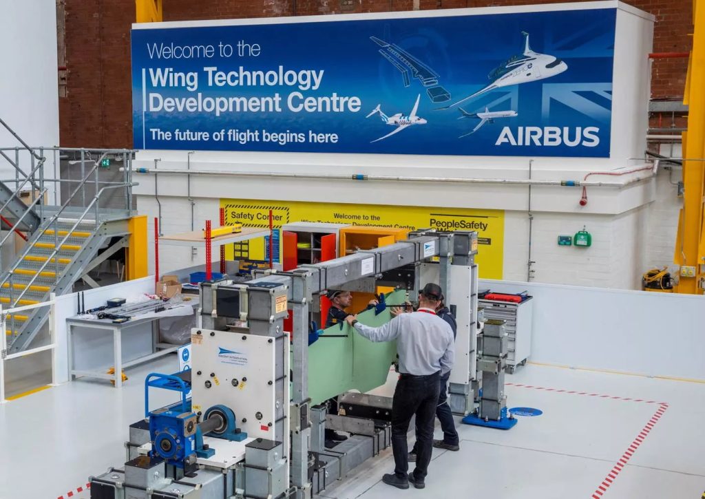
The Wing of Tomorrow (see Figure 1) project led by Airbus is an example of a future composite wing demonstrator with a considerably reduced part count, which, in the process, incorporates innovative manufacturing methods. Airbus was joined in this project by the UK – National Composites Centre and the UK – Royal Aeronautical Centre.
Figure 1: The Wing of Tomorrow, Research Project
Additive Manufacturing (AM) is a new technology addition to aircraft manufacturing. This novel manufacturing method is analogous to 3D printing and will allow for the production of lighter parts with shapes that are not possible with traditional manufacturing methods. AM accomplishes many improvements by building parts with complex geometries and providing a more efficient prototyping platform, allowing quicker creation and testing of parts. Production can be cost-effective since AM material is not wasted (i.e. machined to final form). This technology enables entire parts to be designed to include hollow centers and interior components without weak and vulnerable joints. In additive manufacturing of airplane parts, there is no need to use joining components such as bolts and screws as these parts are one-piece already.
Not only does additive manufacturing reduce fuel consumption, but it also increases the aircraft’s overall strength. With these benefits, additive manufacturing processes can reduce aircraft frame weight by 25% while increasing structural integrity.
As a last point, the aerospace industry has one of the most notoriously long supply chains of any industry. Many aerospace companies stockpile large quantities of components in warehouses to have parts available, raising significant cost and logistical concerns. The post-pandemic period is highly focused on reducing these supply chains’ length and complexity.
Structural health management regimes for aerospace can allow and support smaller and lighter parts whose performance and integrity will constantly be monitored.
Building more integrated structures that reduce assembly, part count, and weight can also support better fuel efficiency. Examples of this are multifunction structures. Figure 2 presents some complex/integrated parts that can be produced using additive manufacturing and other traditional methods.
Figure 2 – Complex Aerospace Parts
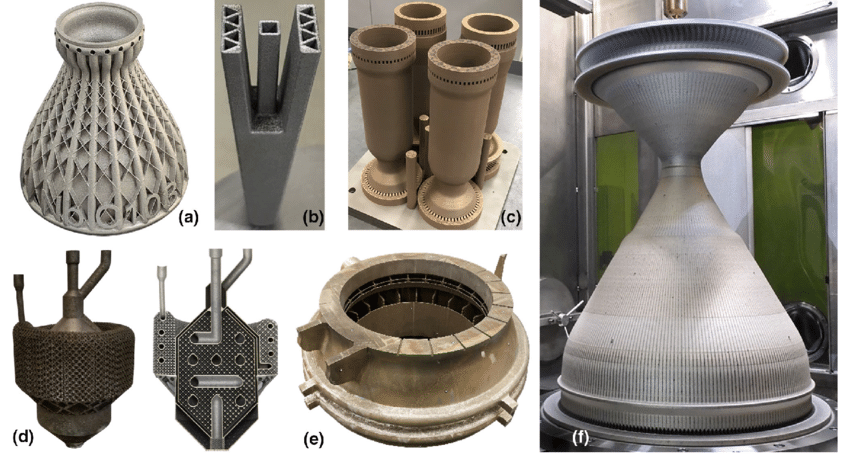
Figure 2 shows complex aerospace parts fabricated with different metals and alloys. These parts are in turn: (a) Actively-cooled thruster using L-PBF C-103 [Courtesy: Castheon], (b) Actively-cooled control surface with L-PBF tungsten, (c) L-PBF GRCop-84 combustion chambers, (d) Mass-optimized AlSi10Mg cryogenic propellant injector along with section to demonstrate internal features, (e) 600 mm diameter L-PBF Inconel 718 integrated heat exchanger, (f) Nuclear Thermal Propulsion Chamber fabricated with NASA HR-1 LP-DED
2. Development of high power density, small core demos
While there are significant improvements in energy use in flight from the next generation of tube and wing aircraft, these gains will gradually become more expensive and difficult to achieve over time. This is because the technological interdependencies start cancelling out their theoretical benefits.
For example, currently under development, ultrahigh bypass ratio engines could theoretically provide a lower specific fuel consumption. Still, the extra drag and weight of the engine (due to its increased size) and the associated cascade effects on the mass of the entire aircraft could cancel these benefits. Higher aspect ratio wings would enable further reductions in drag and thereby improve energy efficiency in flight. However, these wings could now be heavier and require larger engines to achieve the same take-off, climb and cruise performance.
Ultra-long swept wings could also move the center of gravity aft (to the back), posing further challenges to the positioning of the undercarriage and the aircraft’s ground stability. These design interdependencies, including others such as safety requirements or cabin comfort, are constantly carefully studied and accounted for by OEMs.
The Hybrid Thermally Efficient Core (HyTEC) Project (Figure 3) is one example of a high-power density small core engine. This project aims to accelerate the development of the next-generation small-core turbofan engine technologies while improving efficiency, durability, performance, hybridization, and sustainability to meet the next Entry into Service (EIS) for single-aisle aircraft, which are expected in the 2030s.
Figure 3: Proposed HyTEC Small Core Gas Turbine Engine
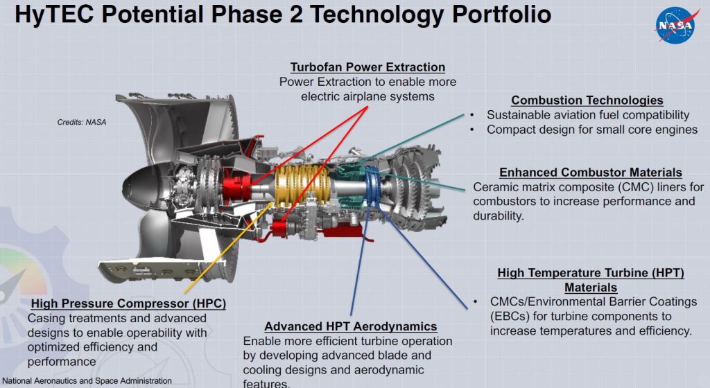
The HyTEC engine aims to achieve a 5-10% fuel burn reduction versus the 2020 best-in-class while achieving up to 20% power extraction (4 times the current state of the art) at altitude to optimize propulsion system performance and enable hybridization.
The term Hybridization refers to the opportunity of the aircraft to use several energy sources in flight, either in tandem or alternately. More will be said about this in a later web story.
These small core technologies, such as the HyTEC project, are aligned with future single-aisle propulsion products, which require a target engine thrust of 25,000 – 35,000 lbf and an engine bypass ratio of > 15.
3. UHBPR, Low NOx engine flight test
This subtitle is acronym-loaded and comes from the IATA technology roadmap under consideration.
The acronyms refer to Ultra High Bypass Ratio (UHBPR) and Low Nitrous Oxides (NOx). Rolls-Royce has built a demonstrator engine called the Ultrafan, which captures these capabilities. That gas turbine engine is slated to enter into service (EIS) in 2030.
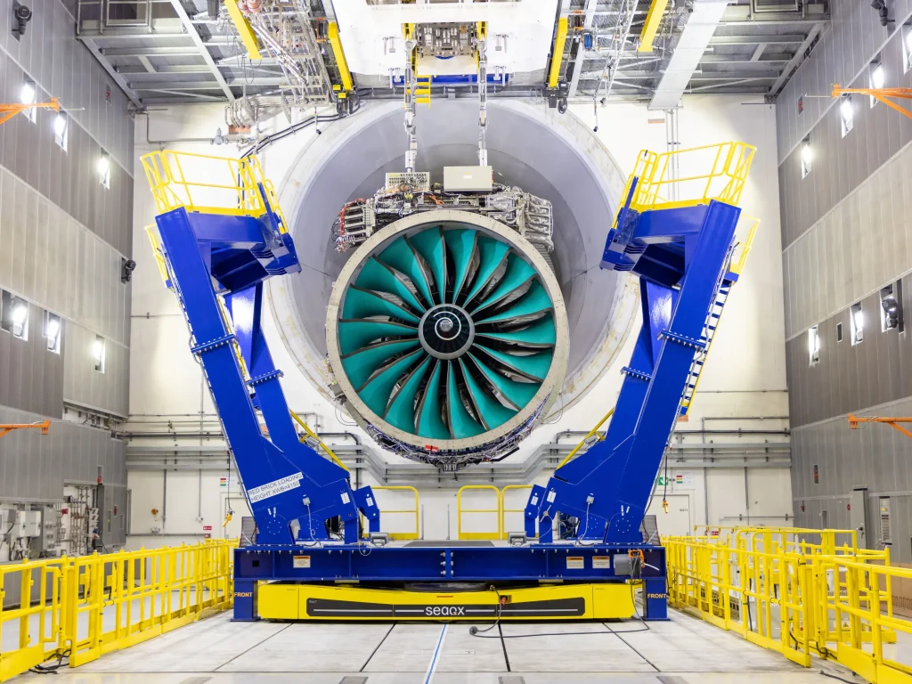
The UHBPR gas turbine engines have a much larger fan than those currently in deployment; this gives them unique properties. The current model of this technology, the Rolls-Royce Ultrafan in particular, has a 140” diameter fan. Ultrafan is the world’s largest aerospace engine, and it can produce 64 MW of power. With a few potential variations on its size, this gas turbine engine can be configured to produce up to 110,000 lbs of thrust (lbf). Figure 4 shows the relative size of this engine in its purpose-built test bed.
Figure 4: Rolls-Royce Ultrafan, demonstrator on stand
The UltraFan aims for a 15:1 bypass ratio and 70:1 overall pressure ratio. These ratios are currently not available in commercial jet engines. As a first opportunity to deploy the UltraFan, it is being considered for the Airbus A350, which is a long-range, wide-body twin-engine jet airliner. The A350 had its first flight in 2013, and Airbus has since built 571 aircraft. Other aircraft with possibilities for Ultrafan deployment are the A330neo, the 787 and the A320neo. At this rate, the Ultrafan would be a “neo” or New Engine Option for all aircraft, allowing buyers to specify this engine as part of their their procurement decision.
The challenge in designing gas turbines with higher pressures is that Nitrous Oxide (NOx; NO and NO2) production increases as the engine core pressure rises. The same case exists for the engine noise levels. NOx is a significant component of harmful air pollution, and building technologies or regimes that mitigate NOx are very important. On the other hand, noise levels are also of particular concern in areas near airports. In the Ultrafan, these benefits are accomplished by using the high bypass component of the air passing around the engine to avoid the fuel burn but later participate only in the power transfer.
Figure 5: Installation effects of ultra-high bypass ratio engines
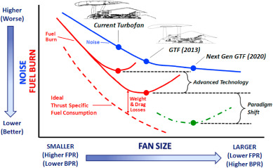
Figure 5 shows the noise levels decreasing as the fuel burn drops, while the fan size also increases when higher bypass ratios are deployed. Several technology shifts are also indicated in Figure 5, with the last case being a paradigm shift to the Ultrafan stage.
Our next web story on the IATA Net-Zero TRM will cover more about electrical control surfaces and the Open Rotor as a means of improving the in-flight energy requirements of aircraft.
References used:
EnviroTREC: World’s largest and most efficient aircraft engine aces first tests