
Two New Engine Architecture plans that remain to be covered from the IATA Technology Road Map are the Counter Rotating Fan and the Ultra High Bypass Ratio Engine.
The Counter Rotating Fan
Counter-rotating fans are positioned in the front of jet engines and spin in opposite directions to each other. The counter-rotating fan concept promises higher efficiency and further noise reduction than current technologies. Additionally, CO2 and NO2 reductions will be significant.
Counter-rotating fans overcome the challenges that jet engine designs face in that as the engine becomes more powerful, they also become more significant. Following this, the engine fan blades (compressor blades) start to be inordinately stressed and rotor tip speeds ,may exceed sonic speeds, thereby creating shock waves in the engine nacelle (i.e. engine compartment).
If rotor speeds become excessive, this would result in shock waves on the compressor blades, which would make the engine unusable. At that point, substantial pressure fluctuations would be found in the nacelle, causing fatigue and failure of blades. Also, the high level of drag developed by supersonic flows would have the effect of slowing the blades down as they rotated.
As a result of the need to lower the blade tip loading and reduce the performance deficit from the significant incidence swing to the rotors, the concepts of the distributed propulsion system and splitting the loading of each rotor into a pair of counter-rotating fans (CRFs) are being adopted in the present designs
The following Figure 1 demonstrate how the counter-rotating fan is located at the front of the engine intake.
Figure 1: Placement of counter-rotating Fan on a jet engine
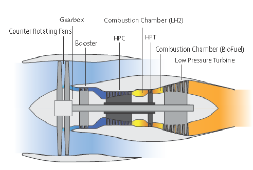
Counter-Rotating Fans are rated as having a Technology Readiness Level of 3[1]. A 15 – 20% fuel efficiency improvement is suggested from the deployment of this technology. Jet engines containing counter-rotating Fans are indicated to enter into service after 2020.
The Ultra-High Bypass Ratio Engine
Discussion on the Ultra High Bypass Ratio Engine begins with the question, “Why is there a need for a high bypass ratio in the first place?”
The answer is that the bypass ratio is the amount of air that passes through the fan—known as “cold thrust”—when compared with the amount of air that passes through the engine core, or combustion chamber, which is called the “hot thrust.” Typically, the higher an engine’s bypass ratio, the better its fuel efficiency.
Technically, the bypass ratio (BPR) of a turbofan engine is the ratio between the mass flow rate of the bypass stream to the mass flow rate entering the core. A 10:1 bypass ratio, for example, means that 10 kg of air passes through the bypass duct for every 1 kg of air passing through the core.
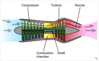
Figures 2, 3 and 4 provide a sequential graphic explanation of what bypass is taking place and how it is accomplished.
Figure 2: High Bypass Jet Engine
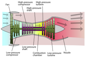
Figure 3: Low Bypass Jet Engine
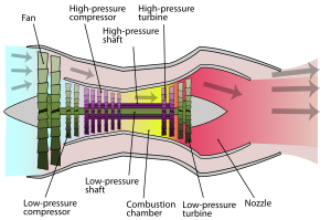
Figure 4: Zero Bypass Jet Engine
Further to the three figures presented above, current jet engines are working with bypass ratios of about 10. These bypass ratios have more or less been implemented over the past decade.
Safran[2] is developing an Ultra-High-Bypass Ratio (UHBR) turbofan engine, which indicates a bypass ratio of at least 15. This design makes extensive use of lightweight composite materials. Their UHBR is expected to have a 5 to 10% fuel efficiency improvement relative to the GE LEAP[3] engine, which is used
in the A320neo family. Fuel efficiency will improve from 20 to 25% when the UHBR replaces conventional jet engines in the narrow-body-airplane category.
The Ultra High Bypass Ratio jet engine is indicated for entry into service by 2025 and is currently evaluated with a technology readiness level of 5 (Component and or breadboard validation in the relevant environment).
The following is now a list of web stories that have been presented on EnviroTREC’s webpages from the IATA Technology Road map
ATA Technology Road Map: New Engine Architecture Concepts 2020 – 2025
Future Technologies – Retrofits and Upgrades to support the Aircraft Technology Road Map
An Aircraft Technology Roadmap to 2050
[1] Analytical and Experimental Critical Function and or Characteristic Proof of Concept.
[2] Safran S.A. – a French multinational company that designs, develops and manufactures aircraft engines, rocket engines as well as various aerospace and defense-related equipment or their components.
[3] https://www.geaviation.com/propulsion/commercial/cfm-leap