
This web story is a continuation of our series on the IATA Technology Road Map. Here we will cover how the aerospace industry proposes to improve efficiencies using retrofits and upgrades.
Aircraft entering service from now to 2030 will have the same overall configuration as their predecessors. Changes proposed during this period will instead be focused on retrofits and upgrades. New aircraft variants and older aircraft will be equipped with retrofits, serial upgrades, newly designed components and systems to improve performance. Each of these elements will individually and uniquely contribute to a higher fuel efficiency performance for the aircraft and ultimately for the fleet.
Table 1 shows an abbreviated list of the most fuel-efficient retrofits and upgrades that manufacturers will install on the current and forthcoming fleet.
| Group | Concept | Type of Technology | Fuel Reduction Benefit |
| Aerodynamics | Winglets | Retrofit | 3 to 6 % |
| Cabin | Lightweight Cabin Interior | Retrofit | 1 to 5% |
| Material and Structure | Active Load Alleviation | Production Upgrade | 1 to 5% |
| System | Structural Health Monitoring | Retrofit | 1 to 4% |
| Advanced Engine Components | Advanced Combustor | Production Upgrade | 5 to 10% |
Source: The preceding table is a condensed version of the IATA TRM (see page 17 of that report for a complete listing)
The complete list of IATA upgrades comprises 16 items which, at a minimum, will contribute 26% to aircraft performance efficiency. Aerospace professionals expect an average of 1.5% per year in fuel efficiency improvements until 2030. On the upside, the entire list of 16 retrofits and upgrades promises as much as 69% in performance improvements.
The following is a further discussion on each of the retrofits and upgrades identified in Table 1.
Winglet – Retrofit
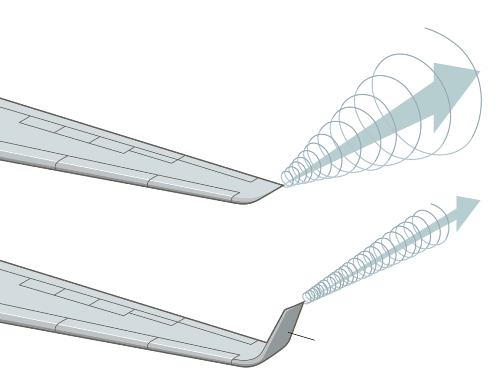
Winglets are vertical extensions of an aeroplane’s wingtips. These winglets improve an aircraft’s fuel efficiency and cruising range. Winglets reduce the aerodynamic drag associated with vortices that develop at the wingtips as the airplane moves through the air. By reducing wingtip drag, fuel consumption decreases, and the range is extended. Winglets in this application serve as small airfoils,
Winglets help mitigate the effects of “induced drag.” When an aircraft is in flight, the air pressure on top of the wing is lower than the air pressure under the wing. This is referred to as “lift”! However, near the wingtips, the high-pressure air from under the wing rushes to the lower-pressure areas on top, creating vortices. These vortices flow in a three-dimensional manner over the wings. Vortices not only pull air up and over the wing, but they also pull air back. This is referred to as induced drag. With the advent of winglets, the aircraft can weaken the strength of wingtip vortices and, more importantly, cut down on induced drag along the whole wing. Figure 1 shows the effect that winglets have on reducing wingtip drag.
Figure 1: Effect of winglets on reducing wingtip drag
The concept of winglets originated with a British aerodynamicist in the late 1800s. However, the idea remained on the drawing board until rekindled in the early 1970s by Dr. Richard Whitcomb when the price of aviation fuel started spiralling upward.
Aircraft manufacturers and makers of add-on winglets have reported improved cruising speeds, time-to-climb rates, and higher operating altitudes. Some airlines report saving as much as 2 million litres of aviation fuel through this innovation.
Cabin – Retrofit
Lightweighting the cabin interior is an ever-pressing concern. Also, if seats can be made thinner, more seats can be added to the cabin, reducing the fuel required to transport each passenger. These innovations are less of an engineering challenge and are somewhat more of a materials management challenge. As new and appropriate materials are proven to be effective, they can be deployed in cabin retrofits.
Cabin retrofits come with other challenges as these new materials must promote passenger safety, comfort, and well-being. While saving space and weight, these materials need to provide fire, smoke, and toxicity compliance. Ozone and volatile organic compounds also need to be mitigated in cabin-air environments. As many will appreciate, newly manufactured foams, threads and materials from the petrochemical industry will also off-gas. Cabin seat swap-outs are also regular events, ranging from rebranding for marketing colour consistency to replacement of worn and damaged cabin elements – making this an optimal time to introduce lighter-weight seats and other cabin fittings. Some airlines have estimated that losing a pound (0.45kg) in weight from every plane in its fleet would save 53,000 litres of fuel a year – adding up to considerable savings each year.
Active Load Alleviation – Production Upgrade
Active Load Alleviation refers to the need for an aircraft to reduce loads (i.e. stresses), particularly to the wings, which arise during maneuvers and turbulence. Load alleviation is integrated into the aircraft’s conceptual design. Designing the aircraft with the simultaneous application of maneuver load alleviation and gust load alleviation can improve fuel burn and direct operating costs. This is accomplished by considering the materials and structure in the design process.
An example of active load alleviation is demonstrated in the following YouTube video (A380 waving aileron).
In the A380, the active load alleviation system is nicknamed “valse des aileron” (Waltz of the Ailerons) because of the dancing movements of the aileron. The Load Alleviation Function (LAF) aims to alleviate the fatigue and static loads on the wings by reducing the wing’s bending.
How fuel efficiency enters into this discussion is that aircraft design is dynamic. As active load alleviation designs are effected, the aircraft’s weight is reduced, reducing fuel costs during the aircraft’s operation. These changes are considered a production upgrade as active load alleviation improvements are generally only introduced into new aircraft variants.
Structural Health Monitoring – Retrofit
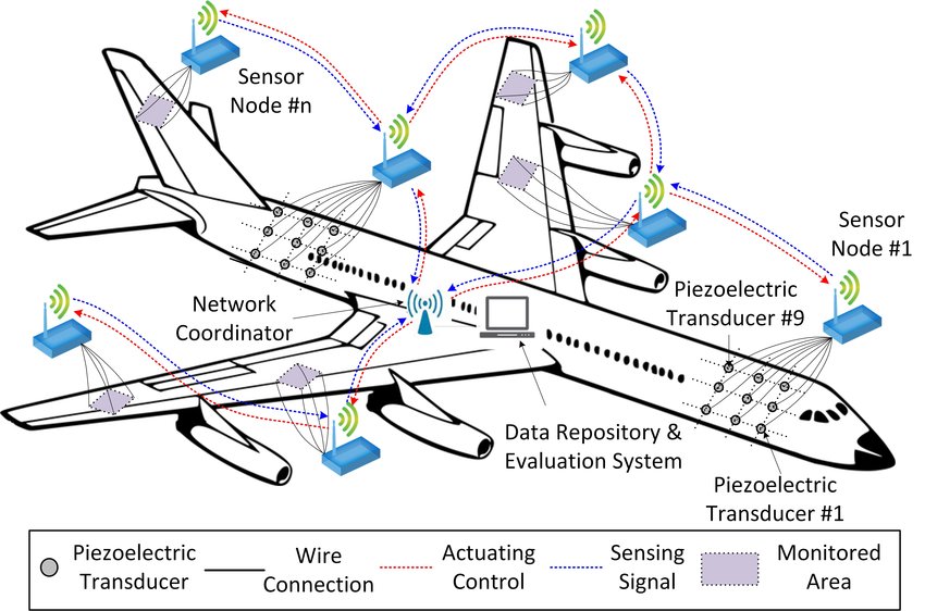
Structural health monitoring (SHM) uses nondestructive inspection principles such as built-in sensors that automatically and remotely assess an aircraft’s structural condition in real-time while also signalling maintenance requirements. SHM assists in fuel economy because it delivers ongoing information about the performance of an airplane – allowing for redesign, which will ultimately reduce its weight! Sensors that support SHM can also be retrofitted. Figure 3 shows a schematic of an aircraft cyber-physical system for SHM, which uses Piezoelectric Transducers (PZTs), active sensing, and a wireless sensor network (WSN).
Figure 2 – Schematic of the cyber-physical system for SHM using Piezoelectric Transducers, Active Sensing and a Wireless Sensor Network.
Advanced Combustor – Production Upgrade
In this case, the fuel efficiency challenge is moved over from the airframe manufacturers to the Gas Turbine Manufacturers, which principally include Rolls-Royce, Pratt & Whitney and General Electric. They are tasked here to provide a new class of combustors. These new combustors will need to perform at high combustion efficiencies and lower emission indices; added to this is a need to accept multifuel capabilities (i.e. gaseous and liquid fuels, including biofuels) and to handle low-pressure drops.
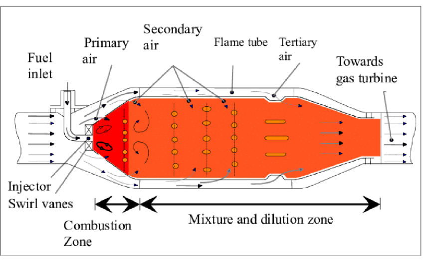
One of these new combustor technologies is the trapped vortex combustor (TVC) which may be considered a very promising form of technology for both pollutant emissions and pressure drop reduction. The TVC is based on mixing hot combustion products and reactants at high rates. Turbulence occurring in a TVC combustion chamber is “trapped” within a cavity where reactants are injected and efficiently mixed. When turbulent combustion occurs inside this cavity, a turbulent flame is anchored utilizing recirculation zones where reactants can mix and burn. Figure 3 provides a diagram of the working principles of the Trapped Vortex Combustor.
Figure 3: Diagram of the working principles of Trapped Vortex Combustors
Another combustor upgrade being considered is the evaluation of ceramic matrix composites (CMC) for gas turbine engines. Advanced CMCs offer significant advantages over the current set of superalloy-based systems, but CMC materials can be brittle and will degrade over time due to high-temperature creep, thermal shock and cyclic thermomechanical loads. Specific innovation research areas include increased thermomechanical durability, increased resistance to environmental interactions, the cost-effectiveness of processing and manufacturing, and improved approaches to CMC combustor component fabrication and integration.
Part of the reason for combustor upgrade ideas is to consider using higher GT operating temperatures, improving thermodynamic efficiencies and, ultimately, airplane performance. Thus far CMC’s have proven to be tough, lightweight and capable of withstanding temperatures 300–400 degrees F hotter than metal alloys can endure.
Figure 4: Main Components of a Gas Turbine engine and the unique materials being used
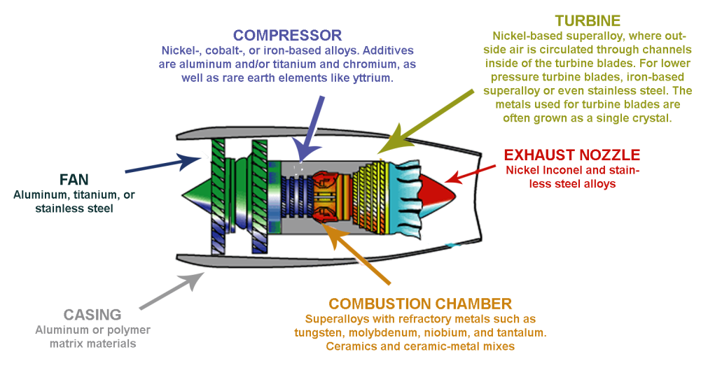
Figure 4 demonstrates the variety of unique materials used in the manufacture of a Gas Turbine Engine. Noted is that CMCs are found in the Combustion Chamber.
The preceding story provided five examples from a list of 16 retrofit and production improvements that the IATA stakeholders see forthcoming in the 2030 timeframe. Aircraft fuel efficiencies from these improvements will be range from 26% to possibly as high as 69%, with an annual improvement of 1.5% expected.
Materials in this presentation have been taken from the Aircraft Technology Roadmap Report as well as from www.NASA.gov and ResearchGate.
Our intent with web pages such as this is to take pieces of that report and represent them with a focus on how aviation will transition from the current state to a Green Aviation state.
If you have a Green Aviation story to tell and would like to publish it on our web pages, please contact us.